In electromagnetic and electro-hydraulic brake systems, “it has power” does not mean “it is correctly powered.” Many field issues—weak release, dragging and overheating, coil burnout, unstable actuation—trace back to one root cause: coil configuration does not match the site electrical system. This includes wrong voltage selection, wrong rectifier type, incorrect wiring for dual-voltage coils, or voltage drop at the brake terminals.
This article explains how to think about coil configuration across common industrial power systems (110V / 220V / 380V), what to verify on site, and how to specify coil power requirements clearly in RFQs. We reference our product families such as SE electromagnetic fail-safe brakes and brake power supply/rectifier boxes (e.g., DKZ series), plus electro-hydraulic systems where coils/controls still matter (thrusters, valves, switches).
[Image Placeholder] Terminal box photo: coil leads + rectifier module + wiring diagram label (highlight “AC in / DC out”).
1) AC coil vs DC coil: don’t assume by voltage alone
Industrial brake coils may be designed as:
- AC coils (powered directly by AC)
- DC coils (powered by DC, often via a rectifier supplied from AC)
Many modern industrial brakes use DC coils even on AC mains because DC coils can provide stable force and predictable response (depending on design). That means on a 220VAC site, you may still need a rectifier to supply ~180–200VDC to the coil, or a defined DC value per the brake design.
First check: read the brake nameplate and wiring diagram. Confirm whether the coil expects AC or DC at the coil terminals.
2) Why coil voltage matters: electromagnetic force and heat are both voltage-sensitive
A coil is an electrical load. If the voltage is too low, magnetic force drops and the brake may not fully release (dragging). If voltage is too high, coil power increases and overheating/burnout risk rises.
For a simplified resistive model:
I \approx \frac{V}{R},\quad P \approx V\cdot I \approx \frac{V^2}{R}Even though real brake coils are inductive and temperature-dependent, the power trend is still directionally correct: power roughly scales with V². A 10% overvoltage can push power up ~21%, which can be enough to turn a “warm coil” into a “hot coil,” especially in enclosed or high-ambient installations.
Field reality: undervoltage is more common than overvoltage because of long cable runs and poor rectifier selection. Undervoltage causes weak release and is a frequent root cause of dragging and brake overheating.
3) Common site power systems and what they imply for brake coils
Below is a practical mapping of common industrial supply systems to brake coil considerations. Final wiring must follow the brake’s own diagram.
| Site power system | Typical brake coil scenario | What to confirm | Typical failure if mismatched |
|---|---|---|---|
| 110VAC control supply | Rectifier to DC coil, or 110VAC coil | Coil rated voltage & rectifier input rating | Weak release if wrong rectifier; coil overheating if wrong coil |
| 220VAC single-phase control | Very common for brake rectifiers powering DC coils | Rectifier output DC and coil requirement | Dragging (undervoltage), slow response |
| 380VAC three-phase main power | Main power for motors/thrusters; brake coils often still use 220VAC control | Don’t feed coil directly from 380VAC unless designed for it | Immediate coil damage if wrong connection |
Key point: Many sites have 380V motors but 220V control circuits. Brake coil supply usually follows the control voltage, not the motor voltage. Always confirm what voltage is available at the brake control output.
4) Rectifiers and brake power supply boxes: small components that decide release speed
When a brake uses a DC coil, the rectifier type matters for:
- Release time: fast-acting rectifiers can reduce delay
- Coil heating: some circuits use economy modes (high pull-in, low hold)
- EMI/overvoltage: suppression protects contacts and electronics
In our supply scope, brake power supply/rectifier solutions (e.g., DKZ series brake power supply boxes) are commonly used to match AC input to the correct DC output and to provide stable performance. Using an incorrect rectifier is a common cause of “brake opens weakly” or “coil runs hot.”
Two on-site measurements that reveal rectifier problems quickly
- Measure DC voltage at the brake coil terminals during release (not only at the cabinet).
- Measure coil current with a clamp meter (or series meter) and compare to expected baseline.
If coil voltage at the brake is low, check cable sizing, wiring errors, rectifier input voltage, and whether the rectifier is sized for the coil current.
5) Cable voltage drop: why a “correct 220V cabinet” becomes “190V at the brake”
Long cable runs can drop voltage. For DC coils, this directly reduces release force. A simple estimate for voltage drop is:
\Delta V \approx I \cdot R_{wire}And wire resistance depends on length and cross-section. The practical implications:
- higher coil current → higher voltage drop
- longer cables → higher voltage drop
- smaller cross-section → higher voltage drop
Field symptom: brake releases fine when cold/no load but starts dragging after heating (clearance changes), because the coil never had enough margin due to undervoltage at the terminals.
6) Dual-voltage coils and wiring options: series vs parallel (why wrong wiring causes weak force or burnout)
Some coil designs allow different supply voltages by changing how windings are connected (series vs parallel). This is common in motors and appears in some electromagnetic components. The important point is: the correct connection is part of the brake configuration.
Practical warning: wiring a coil intended for 220V operation as if it were 110V (or vice versa) can cause either:
- weak release (undervoltage on winding)
- overheating/burnout (overvoltage on winding)
If the terminal box includes a wiring label, photograph it and confirm it matches the site supply before energizing.
7) Coil configuration checks by brake type (what technicians should actually verify)
SE electromagnetic fail-safe brakes
For SE series, the most important on-site checks are:
- coil rated voltage and type (AC/DC) vs actual supply
- rectifier/power supply matches coil requirement (if DC coil)
- air gap setting is within specification (too large = weak force even with correct voltage)
- measure coil terminal voltage under actuation (catch voltage drop)
SE Series Electromagnetic Fail-Safe Brake
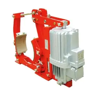
Electro-hydraulic thruster brakes (YWZ/YWZ13)
Thruster brakes are motor-driven, so coil issues are less central than on electromagnetic brakes, but control voltage still matters for:
- thruster motor supply (correct V/Hz)
- brake-open switches and interlocks
- solenoid valves (if part of the brake system)
Wrong thruster motor supply (e.g., wrong frequency) can change stroke speed and increase heating. Always confirm supply at the thruster terminals, not only at the panel.
YWZ13 Series Electro-Hydraulic Drum Brake
8) A compact on-site checklist (copy/paste)
- Read nameplate: coil type (AC/DC), rated voltage, series/model.
- Confirm site control supply voltage (110/220) and frequency (50/60 Hz).
- If DC coil: confirm rectifier input rating and expected DC output.
- Measure voltage at brake coil terminals during release (record value).
- Measure coil current (record value) and compare to baseline/spec.
- Confirm air gap/clearance is within spec (electrical fixes can’t overcome a wrong gap).
- After first hot run, re-check release quality (dragging is often marginal-voltage related).
Need help matching your brake coil/rectifier to your power system?
If you share your brake model (e.g., SE), coil rated data from the nameplate, your site supply (110/220/380, 50/60Hz), and cable length to the brake, we can recommend a correct coil/rectifier configuration (such as a DKZ brake power supply box), and suggest what terminal voltage you should expect after installation.