A brake guard is often treated as a simple safety cover—something to satisfy site rules and keep hands away from rotating parts. In real industrial duty, the guard becomes part of the brake system: it changes airflow, temperature rise, dust ingress, and how quickly a technician can inspect or replace wear parts.
We see two common field outcomes when guard design is not considered carefully: (1) brakes that run hot and wear fast (because the guard traps heat or causes dragging inspections to be skipped), and (2) brakes that fail early in dusty environments (because the guard does not actually block the dust paths that matter). This article explains practical guard design choices for industrial brakes, referencing typical applications of our products such as YWZ13 electro-hydraulic drum (block) brakes and SH hydraulic fail-safe disc brakes.
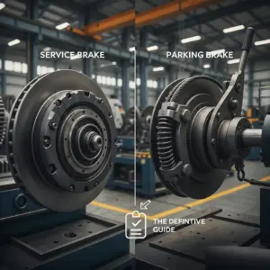
[Image Placeholder] Two guards compared: fully closed cover vs louvered/perforated cover with inspection windows and drain points.
1) What a brake guard must achieve (and why “more closed” is not always safer)
A good brake guard has to satisfy four requirements at the same time:
- Personnel protection: prevent accidental contact with moving parts, hot surfaces, and pinch points.
- Contamination control: reduce dust, water spray, and foreign objects entering the friction area and linkages.
- Thermal performance: allow the brake to reject heat so torque remains stable and seals/coil insulation life stays reasonable.
- Maintainability: allow inspection and service (air gap / clearance checks, pad/lining replacement, manual release access) without removing half the machine.
On cranes, conveyors, and wind/winch systems, the “guard vs cooling” conflict is real. In many field cases, a fully enclosed guard can increase stabilized brake temperatures by tens of degrees compared with a ventilated design—enough to accelerate glazing, oil seal aging, and even create fade risk under high stop frequency. That’s why guard design should be validated together with your duty cycle (ideally in a temperature rise test with the guard installed).
[Internal Link Placeholder] Link to your earlier article: Brake temperature rise test design (useful for guard validation).
2) Cooling basics: the two design variables you can control (open area and airflow path)
For most brake guards, you are not “adding cooling”—you are deciding how much cooling you remove. Two variables matter most:
- Vent open area ratio (how much air can pass through)
- Airflow path (whether air actually crosses the hot friction surfaces)
A simple way to quantify ventilation is open area ratio:
\text{Open Area Ratio}=\frac{A_{open}}{A_{total}}\times 100\%Practical starting points (field-proven tendencies):
- Indoor / light dust: perforated or louvered guards commonly work well when open area ratio is roughly 30–50%.
- Outdoor / wind-driven rain: use louvers + drip edges + downward-facing openings; keep airflow but block direct water entry.
- Heavy dust (cement, coal, ore): don’t rely on “more holes.” Use controlled airflow paths (labyrinth + louvers) and easy cleaning access.
Airflow path matters more than holes: A guard can have many perforations yet still trap heat if there is no clear inlet→outlet flow across the disc/drum area. Whenever possible, create a cross-flow: cool air enters low on one side and exits high on the opposite side (hot air naturally rises).
[Image Placeholder] Guard airflow diagram: inlet louvers (low), outlet vents (high), flow arrows across friction track.
3) Dust protection: block the real ingress routes (not just “cover everything”)
Dust problems in brakes usually come from one of these mechanisms:
- Abrasive ingress into friction interface (accelerates wear, scoring, hot spots)
- Dust packing around pivots and linkages (causes sticking → incomplete release → dragging → heat)
- Oil + dust paste (from nearby gearboxes or hydraulic leaks) that creates unstable friction and glazing
Guard features that work in real dust:
- Downward-facing louvers instead of straight holes (blocks direct dust jet entry).
- Labyrinth edges at seams (overlap joints rather than simple butt seams).
- Drain and clean-out points (dust will accumulate; design for removal rather than “trying to keep it out forever”).
- Non-clogging mesh strategy: fine meshes block dust but clog fast; if you use mesh, make it removable and easy to clean.
Practical warning: In mining/cement duty, overly fine screens often become “dust filters” that block airflow—then temperature rise becomes the next failure mode. Many sites are better served by louvers + periodic clean-out than by fine mesh.
4) Maintenance access: design for the tasks technicians actually do
If a guard makes inspection annoying, inspection won’t happen—especially for items like clearance, pad thickness, and leakage checks. Design access around these common tasks:
- Clearance checks: air gap (disc brakes) or shoe clearance (drum/block brakes)
- Pad/lining wear checks: visual access to friction thickness without full disassembly
- Manual release access: especially for fail-safe brakes used on hoists/winches
- Fastener witness-mark checks: ability to visually confirm bolts haven’t moved
Two guard choices that reduce downtime immediately:
- Inspection windows (small cutouts with removable covers) at measurement points.
- Quick-release hardware (hinged panels, captive bolts) so a guard can be opened in minutes, not hours.
[Image Placeholder] Example: hinged guard panel with captive bolts + window showing pad thickness gauge point.
5) Material, thickness, and corrosion: the guard has to survive the same environment as the brake
Guard material selection should be based on environment and vibration. Typical options:
- Carbon steel sheet with industrial coating (most common, cost-effective)
- Stainless steel for severe corrosion (ports/offshore), but consider galvanic pairing with carbon steel frames
- Aluminum for weight-sensitive designs, but confirm stiffness and vibration behavior
Practical thickness ranges (typical): many industrial brake guards use roughly 1.5–3.0 mm sheet thickness depending on span, vibration, and impact risk. Too thin can resonate and crack; too thick can trap heat if ventilation is poor and makes service harder.
For coastal/port duty, specify a corrosion system clearly (surface preparation + coating stack + hardware choice). A “guard that rusts” quickly becomes a guard that rattles, loosens, and blocks inspection.
6) Product-oriented design notes (what to watch on common brake families)
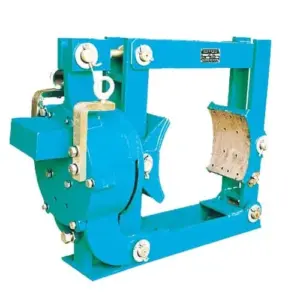
YWZ13 electro-hydraulic drum (block) brakes: protect linkages, but don’t block thruster cooling
On YWZ13 and similar electro-hydraulic drum brakes, many overheating complaints come from partial release (dragging) due to linkage issues or thruster stroke problems. A guard should:
- keep abrasive dust away from pivots and return paths
- provide an access point to check shoe clearance symmetry
- avoid enclosing the thruster motor in a stagnant hot pocket (thrusters need airflow for longevity)
- include drainage/clean-out (dust and water will accumulate)
[Internal Link] YWZ13 Series Electro-Hydraulic Drum Brake
SH hydraulic fail-safe disc brakes: protect the disc, keep inspection simple, preserve release margin
For SH hydraulic fail-safe disc brakes, the guard must not interfere with pad retraction or hide early signs of drag. Recommendations:
- provide a clear inspection line for pad thickness and disc surface condition
- ensure the guard does not contact the disc at any deflection state (allow for thermal growth and shaft movement)
- avoid oil-trap designs: if hydraulic mist or nearby gearbox oil reaches the guard, it should not drip onto pads
- if used outdoors, use louvers to block direct rain while keeping cross-flow
[Internal Link] SH Series Hydraulic Fail-Safe Disc Brakes
7) How to validate a guard design (simple tests that prevent expensive redesign)
You don’t need a complex lab to prove whether a guard works. These three checks catch most issues early:
- Thermal check: run a representative duty cycle with the guard installed and record temperature rise at the friction area and actuator (compare “guard on” vs “guard open” if possible).
- Dust behavior check: after a week of real operation (or simulated dust exposure), open the guard and observe where dust accumulates—then redesign vents/clean-out points based on real deposition paths.
- Service time check: time how long it takes to measure clearance and inspect wear. If it takes too long, it won’t be done routinely.
[Image Placeholder] Field IR scan of disc/drum with guard installed showing hot spots and airflow effect.
Need a guard recommendation for your brake model and environment?
If you tell us your application (crane hoist, crane travel, conveyor, wind/winch), environment (dust type, outdoor/port corrosion), and brake model (e.g., YWZ13, SH), we can recommend a guard concept (perforated vs louvered vs labyrinth), inspection window locations, and a basic validation checklist. On request, we can also supply brake assemblies with matched accessories to reduce commissioning risk.
[Internal Link Placeholder] Contact our team to discuss brake guard options and site requirements.