When an industrial disc brake shows vibration, uneven pad wear, inconsistent stopping time, or unexpected temperature rise, the first suspect is often the caliper or friction material. In practice, many of these problems originate upstream: disc machining accuracy and how the disc is mounted. Two numbers matter most in the field: flatness and runout.
This article explains how disc machining accuracy influences braking stability, how to measure it on site, and how to set practical acceptance limits. Where product examples are relevant, we reference our disc brake solutions such as the SH series hydraulic fail-safe disc brakes used in high-duty holding and emergency applications.
[Image Placeholder] IR image of a disc showing a “hot band” caused by runout/uneven contact.
1) Flatness vs runout: two terms people mix up
Flatness describes how close a disc surface is to a perfect plane. It’s a property of the surface itself (manufacturing quality). Runout describes how much the disc wobbles as it rotates relative to the caliper—usually measured as Total Indicated Runout (TIR). Runout includes effects from:
- disc machining error
- mounting face error (hub/flange)
- fastener torque pattern and debris between faces
- bearing play and shaft deflection
In other words: a disc can be very flat but still have large runout if the mounting is poor. And a disc with small runout can still cause unstable friction if the surface flatness/parallelism is inconsistent across the track.
[Image Placeholder] Simple diagram showing flatness (surface plane) vs runout (wobble during rotation).
2) Why accuracy matters: the chain reaction that causes vibration and heat
Disc accuracy problems create a predictable chain reaction in industrial braking:
- Runout → pad knock-back: the disc pushes pads away each rotation. Next stop starts with a larger air gap, delaying full torque.
- Uneven contact → local hot spots: small areas carry most load, causing temperature spikes and glazing.
- Hot spots → friction drift: torque becomes inconsistent across stops; noise and judder increase.
- Thermal distortion → more runout: heat warps the disc, amplifying the original issue.
For fail-safe holding systems (wind turbines, winches, hoists), delayed engagement or uneven holding contact can also show up as “micro slip” or creep during hot conditions—often misdiagnosed as “weak brake pressure.”
3) What to measure (and where): a practical inspection plan
You don’t need a metrology lab to catch most disc issues. A dial indicator, a magnetic base, and good measurement discipline cover the majority of field acceptance.
A) Runout (TIR) measurement
Tooling: dial indicator (0.01 mm resolution is usually sufficient) + magnetic base. Where: measure on the friction track, not on the outer edge. How:
- Clean the disc and hub/flange contact surfaces (rust flakes and paint can create false runout).
- Mount the indicator so the tip contacts the friction track near mid-radius.
- Rotate one full revolution and record TIR (max minus min).
- Repeat at two radii (inner and outer track) if possible to see tilt effects.
[Image Placeholder] Dial indicator setup on disc friction track showing how to record TIR.
B) Disc thickness variation (DTV) and parallelism (often the hidden cause)
Even if runout looks acceptable, thickness variation across the disc can cause torque ripple and vibration. Use a micrometer to measure disc thickness at multiple points around the circumference (e.g., 8–12 points), at the same radius. Large variation indicates machining or thermal distortion.
Practical note: many “judder” complaints correlate more strongly with thickness variation than with runout.
C) Surface finish (Ra) and machining pattern
Disc surface finish influences bedding-in, noise, and pad wear. A surface that is too smooth can encourage glazing; too rough increases wear and heat. If you have a portable roughness tester, record Ra. If not, at least visually confirm the machining pattern is uniform and free from deep tool marks.
[Image Placeholder] Photos comparing acceptable machining marks vs deep tool grooves that will create hot spots.
4) Setting acceptance limits: what is “good enough” for industrial brakes?
Acceptance limits depend on disc diameter, shaft speed, caliper stiffness, and air gap setting. Rather than publishing one universal number, use a tiered approach that matches risk:
| Application tier | Typical risk profile | Suggested focus | Common acceptance approach |
|---|---|---|---|
| General industrial positioning | Moderate duty, lower consequence | Runout + basic surface check | Set TIR target + verify no hot spots after bedding |
| High-duty travel braking | Frequent stops, heat sensitive | Runout + DTV + surface finish | Tighten TIR and track thickness variation |
| Safety-critical holding / emergency | Fail-safe holding, high consequence | Runout + parallelism + mounting face | Include hot holding verification + runout stability check |
If you need a simple way to tie runout to your brake’s clearance margin, you can treat the “effective air gap disturbance” as a portion of runout. In practice, if runout is a significant fraction of your set air gap, you will see pad knock-back and delayed engagement.
Practical rule of thumb (field screening): if measured TIR is large enough that you can see the caliper/pad movement by eye during slow rotation, it’s already too high for stable braking.
5) The most common root causes of excessive runout (and quick fixes)
- Dirt/paint between disc and hub: remove, stone the surface, re-mount.
- Uneven bolt tightening: use a star pattern and torque in steps.
- Distorted hub/flange: measure hub face runout separately; fix the mounting base, not only the disc.
- Bearing play: check shaft movement; braking stability won’t improve until bearings are corrected.
- Thermal distortion: investigate dragging or undersized brakes causing overheating; replacing discs without fixing heat source repeats the failure.
[Image Placeholder] Mounting face inspection: showing how a small burr creates measurable runout.
6) How disc accuracy links to our brake product performance (what customers feel)
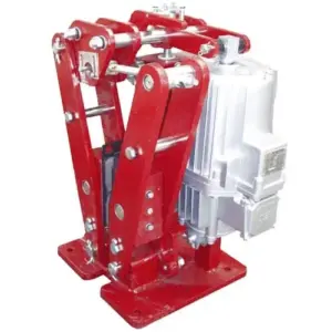
Disc machining accuracy is not a “disc supplier issue” only—it directly affects caliper brakes. For example, our SH hydraulic fail-safe disc brakes are widely used for holding and emergency braking where predictable engagement is required. If the disc has excessive runout, the brake can show:
- delayed full clamp due to pad knock-back
- uneven pad wear and frequent adjustment needs
- localized hot bands on the disc (thermal instability)
- noise/judder complaints even when hydraulic pressure is stable
That’s why we recommend treating disc/hub inspection as part of brake commissioning. In many projects, correcting runout reduces “brake problems” without changing the brake model at all.
[Internal Link Placeholder] SH Series: commissioning checklist (includes disc runout check and pad clearance verification).
7) A short, usable on-site acceptance checklist (copy/paste for technicians)
- Clean disc and hub faces; confirm no paint, rust flakes, burrs.
- Measure disc runout (TIR) at friction track; record value and radius.
- Measure thickness at 8–12 points (same radius); record max-min.
- Visually inspect machining pattern; confirm no deep grooves.
- Torque disc mounting bolts in star pattern; re-check TIR after torque.
- After bedding-in, IR-scan disc after typical stops to detect hot bands.
Need help defining runout/flatness limits for your disc size and duty cycle?
If you share disc diameter, shaft speed, brake model (e.g., SH), and target air gap, we can suggest practical acceptance limits and the measurement points to record. That makes it much easier to align brake performance expectations between the brake supplier, disc supplier, and the site commissioning team.
[Internal Link Placeholder] Contact our engineering team for disc accuracy acceptance criteria and commissioning support.