“Brake torque” looks like a single number on a datasheet, but in real machines it behaves differently at zero speed versus rotating conditions. That’s why many brake disputes happen after commissioning: the brake passes a static holding test, yet dynamic stopping feels weak (or harsh), overheats, or shows inconsistent repeatability.
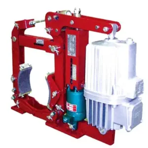
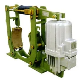
This article explains two practical ways to measure industrial brake torque—static load torque testing and dynamic brake testing—and why their results often differ. Where product examples are needed, we reference our common crane and heavy-industry brake families such as YWZ13 electro-hydraulic drum (block) brakes and SH hydraulic fail-safe disc brakes.
[Image Placeholder] Photo: torque test bench showing brake, shaft, coupling, encoder, and data acquisition.
What “torque” are you trying to prove?
Before choosing a method, define which torque you need to validate. In industrial braking, these are not interchangeable:
- Static holding torque: torque the brake can hold at zero speed without slip (critical for hoists, parking, wind loads).
- Breakaway torque: peak torque right when the locked system starts to move (often higher than steady sliding friction).
- Dynamic braking torque: torque during rotation while decelerating (what determines stopping time and heat).
- Hot torque retention: torque at elevated temperature after repeated stops (fade/consistency indicator).
A static test is excellent for proving holding. A dynamic test is necessary to quantify stopping and thermal behavior. Many projects need both.
Static torque testing (dead weight / lever arm): what it measures well
A static load test measures torque at zero speed by applying an external torque to the brake shaft until the brake slips (or until you reach a specified test torque). It is widely used for factory acceptance and maintenance checks because it is simple, safe, and repeatable—if set up correctly.
The most common setup uses a lever arm of known length and a known force (dead weights or a load cell). The core relationship is:
T = F \times LWhere:
- T = torque (N·m)
- F = applied force (N)
- L = effective lever arm (m), measured perpendicular to force direction
Numeric example (typical shop-floor calculation)
If your lever arm is 0.80 m and your load cell reads 1.20 kN (1200 N), then the applied torque is 960 N·m.
[Image Placeholder] Diagram: lever arm geometry showing “effective length” (perpendicular distance) and cosine error.
Static test procedure (practical checklist)
- Control the direction: for some drum/block brakes, torque can differ by rotation direction due to geometry. Record the direction.
- Define slip criteria: e.g., “shaft moves ≥ 1°” or “continuous rotation occurs.” Without a clear definition, results vary by operator.
- Repeat 3–5 times: record min/avg/max. If repeatability is poor, investigate lining condition, contamination, or mechanical binding.
- State the temperature: cold static torque can differ from hot static torque after a stop sequence.
- Lock out compliance: eliminate rubber couplings or loose fixtures that “wind up” and release energy suddenly.
What static testing can miss
Static torque testing does not fully capture dynamic effects: friction coefficient changes with speed, engagement behavior matters, heat generation matters, and time-to-torque matters. It can also overestimate real stopping performance if breakaway friction is high but sliding friction is lower.
Dynamic torque testing: how stopping torque is measured in rotation
A dynamic test measures braking during rotation. There are two practical approaches:
- Direct torque measurement with an inline torque transducer (best if you have it).
- Inertia deceleration method using speed-time data and known inertia (very common for brake dynamometers).
Method A: Torque transducer (direct)
This approach records a torque curve during the stop. It is ideal when you want to evaluate engagement smoothness, peak torque, and control timing (especially on VFD-driven cranes). Typical sampling rates are 200–1000 Hz for clean curves.
Recommended channels to log (minimum): torque, speed (encoder), brake command signal, brake-open confirmation (if available), and temperature near the friction interface. Without these, “good/bad” conclusions are hard to defend.
Method B: Inertia deceleration (speed-time)
If you know the total equivalent inertia J at the brake shaft and you measure angular deceleration α, you can estimate average braking torque:
T \approx J \times \alphaAnd angular deceleration can be calculated from speed change over time:
\alpha = \frac{\Delta \omega}{\Delta t}Numeric example (realistic for industrial test benches)
Assume a test inertia of J = 25 kg·m². The brake is applied at 600 rpm (ω ≈ 62.83 rad/s) and stops in 3.0 s. Then α ≈ 62.83 / 3.0 ≈ 20.94 rad/s², so the average braking torque is about 523 N·m.
If you also want to estimate the energy the brake turns into heat per stop (useful to connect torque testing with temperature rise testing), you can calculate:
E_{stop}=\frac{1}{2}J\omega^2With the numbers above, Estop ≈ 0.5 × 25 × 62.83² ≈ 49 kJ per stop.
[Image Placeholder] Plot: speed vs time curve for a stop, with highlighted “brake delay” and “effective deceleration window.”
Important: inertia deceleration gives you “system torque” required for deceleration. If there are significant bearing losses, gearbox losses, or aerodynamic load torques, you should quantify them (by a coast-down test without braking) and correct the result if you need high accuracy.
Why static and dynamic torque results differ (and why this is normal)
If your static torque result doesn’t match your dynamic torque result, it’s not automatically a test error. Three real effects drive the difference:
1) Breakaway friction vs sliding friction
At zero speed, friction often shows a higher “breakaway” value before motion starts. During rotation, the friction coefficient is usually different (often lower). Static tests can therefore look “strong,” while dynamic stopping feels weaker. That’s why dynamic testing is essential for stop-time verification.
2) Temperature and fade during the stop sequence
Dynamic tests generate heat. As temperature rises, friction materials can change behavior. A brake can pass cold torque and still lose 10–20% torque at elevated temperature depending on lining material, duty cycle, and airflow. If your application is high frequency (crane travel, hoist inching), hot torque retention matters.
3) Geometry effects (especially on drum/block brakes)
Some drum/block brake geometries can show direction-dependent behavior (self-energizing tendencies). That means torque can differ depending on which way the brake wheel tries to rotate. A well-designed test should specify torque direction and, when relevant, validate both directions—this is particularly practical for crane travel and certain conveyor drives.
A practical test matrix (what many factories and projects actually need)
If you want torque data that is useful for engineering and for customers, test cold and hot conditions and combine static + dynamic checks.
| Test point | Method | Typical purpose | What to record |
|---|---|---|---|
| Cold holding torque | Static load | Parking/holding verification, acceptance baseline | T, direction, slip criterion, ambient |
| Cold stopping performance | Dynamic | Stop time / average torque baseline | speed-time, torque (if available), brake delay |
| Thermal conditioning | Repeated dynamic stops | Heat soak to representative operating temperature | temperatures, stop count, airflow |
| Hot torque retention | Dynamic | Fade/consistency under realistic thermal state | T_hot/T_cold, stop time drift |
| Hot holding check | Static load | Confirm no creep after heat (critical for hoists) | hold time, slip, temperature |
[Internal Link Placeholder] Download: Torque Test Sheet (static & dynamic) + data logging checklist.
Product-focused notes: how these tests apply to common brake types
YWZ13 electro-hydraulic drum (block) brakes
For YWZ13-style electro-hydraulic drum brakes, a static test is useful to confirm holding torque and to detect mechanical issues (misadjusted clearance, binding pivots, uneven shoe contact). But for real stopping behavior—especially on crane travel mechanisms—dynamic testing reveals what static cannot: engagement smoothness, stop-time repeatability, and thermal drift.
Practical recommendation: include two torque directions in your static test plan and record the shoe clearance setting before/after the hot cycle. If torque changes dramatically after heating, investigate dragging or linkage geometry rather than assuming “lining quality” first.
[Internal Link] YWZ13 Series Electro-Hydraulic Drum Brake
SH hydraulic fail-safe disc brakes
Fail-safe disc brakes are often selected for safety-critical holding (hoists, wind, winches). Here, static torque is non-negotiable—but dynamic tests still matter if the brake is expected to perform emergency stops. A good combined plan is: cold static holding → thermal conditioning stops → hot static holding (creep check) → emergency stop verification (if the application requires it and the brake is rated for it).
Also record hydraulic pressure and release behavior. A brake can pass torque but fail in real operation if release is incomplete (dragging), creating heat that lowers torque over time.
[Internal Link] SH Series Hydraulic Fail-Safe Disc Brakes
Electromagnetic brakes (motor brakes / compact units)
Electromagnetic brakes may show strong sensitivity to coil voltage, air gap, and temperature. Static holding checks are useful, but dynamic tests are often where issues appear first: delayed release, delayed engagement, or torque instability under repeated cycling. For meaningful results, log coil voltage at the brake terminals (not only at the cabinet) and confirm air gap is within specification.
Common torque test mistakes (and how to avoid bad conclusions)
- Lever arm “cosine error”: if the force is not perpendicular, your calculated torque is wrong. Measure the perpendicular distance.
- No slip definition: “It moved a little” is not a criterion. Define a measurable slip threshold.
- Ignoring brake delay time: in dynamic tests, torque is not immediate. Separate command delay from effective deceleration window.
- Wrong inertia: if J is estimated poorly, calculated torque is meaningless. Measure inertia or validate with coast-down.
- No temperature context: cold-only torque numbers rarely predict high-duty behavior.
If you want, we can help you choose the right test method for your brake model and application
If you tell us your brake model (e.g., YWZ13 / SH), mounting location (hoist, trolley, bridge travel), target speed, estimated inertia, and duty cycle, we can suggest a practical torque test plan (static + dynamic) and the instrumentation needed to produce defendable results.
[Internal Link Placeholder] Contact our engineering team for an application-based torque test recommendation.