Industrial brake control circuits switch inductive loads all the time: brake coils, contactors, solenoid valves, and sometimes thruster motors. Every switch event can generate a transient voltage spike. If you ignore surge protection, the results are very consistent: relay contacts pit and weld, PLC outputs fail early, rectifiers run hot, and brake release/apply timing drifts over time.
This article explains practical surge (transient) suppression methods for industrial brake circuits, with a focus on the most common configurations: AC supply + rectifier + DC brake coil (typical for electromagnetic fail-safe brakes), and mixed circuits including solenoid valves and brake-open switches. Where product references are relevant, we connect the concepts to our SE electromagnetic fail-safe brakes and brake power supply/rectifier solutions (e.g., DKZ brake power supply boxes).
Control cabinet layout: PLC output → interposing relay → rectifier → brake coil, with surge suppressor locations highlighted.
1) Why surge protection matters specifically for brake circuits
Brake circuits are high-cycle by nature: travel and conveyor brakes may actuate dozens to hundreds of times per hour. That means even “small” transients become cumulative damage.
The root cause is inductance. When current through an inductor is interrupted, the circuit will try to keep current flowing, producing a high voltage spike:
V = L\cdot\frac{di}{dt}Higher inductance, faster switching (large di/dt), and long cable runs all increase surge severity. The spike energy is then dumped into whatever is weakest: relay contacts, transistor outputs, rectifier diodes, or insulation.
2) Identify what you are switching: AC coil, DC coil, solenoid valve, or motor
Surge suppression must match the load and supply type. In industrial brake systems, the most common loads are:
- DC brake coil (often powered by an AC rectifier)
- AC brake coil (less common in some modern designs)
- Solenoid valves (hydraulic/pneumatic brake release circuits)
- Contactors/relays that drive the above
A single cabinet can contain all of these, so it’s normal to use multiple suppression methods in one project.
3) DC coil suppression: diode, TVS, or RC—choose based on timing requirements
Most electromagnetic fail-safe brakes (including our SE series) use a DC coil (often fed by a rectifier). When you switch off a DC coil, you must decide what is more important:
- Protect electronics (lower spike)
- Fast release (faster current decay)
Suppression options trade these off.
A) Flyback diode (simple, very protective, but can slow release)
A diode across the DC coil clamps voltage to ~0.7–1.2 V above supply polarity, which protects outputs very well. But it also allows current to decay slowly, which can increase brake release/apply delay (depending on how the brake is designed).
Use when: coil is driven by sensitive electronics, timing is not extremely tight, and you prioritize component life.
B) TVS diode (faster decay, good protection, common in industrial cabinets)
A TVS clamps at a higher voltage than a simple diode, letting current decay faster while still protecting outputs. It’s a common approach when you need a balance: protection + acceptable brake timing.
Use when: you need faster response than a flyback diode allows, but still want strong electronics protection.
C) RC snubber (more common on AC, but used in mixed cases)
RC networks can be used to limit dv/dt and contact arcing in some switching scenarios. In DC coil circuits, RC solutions are less common than diode/TVS but may appear in certain legacy designs.
Practical commissioning point: whichever method you use, verify the brake’s release/apply time at the mechanism. Suppression choices can change timing enough to affect interlocks.
4) AC load suppression: RC snubber and MOV (varistor) are common
For AC coils (contactors, relays, some solenoids), two methods are common:
- RC snubber across the coil or across the switching contacts
- MOV (varistor) across the AC supply to clamp surges
MOV selection basics: choose an MOV rated for your AC line (e.g., 230VAC or 460VAC classes as applicable), with adequate surge energy rating. MOVs degrade over repeated surges; treat them as maintenance items in high-cycle brake systems.
RC snubber basics: choose snubber values compatible with your coil and switching device. Poor snubber selection can create leakage current that causes “ghost” energization in very sensitive circuits, so verify with your control design.
5) Rectifiers and brake power supply boxes: protect the rectifier and control the release curve
If your brake uses a rectifier (very common), surge protection interacts with the rectifier design. In many projects, using a purpose-matched brake power supply/rectifier (such as our DKZ brake power supply boxes) simplifies correct integration because the rectifier and protection behavior are designed around brake coils and duty cycles.
What to verify in rectifier-based systems:
- AC input rating matches the control supply
- DC output matches the brake coil rating
- suppression method does not slow release beyond interlock limits
- surge protection is placed where it protects the switching device (relay/PLC output)
6) Where to place suppressors (placement is often more important than component choice)
Two placement rules prevent most issues:
- Place suppression close to the inductive load (brake coil or solenoid) to reduce cable-induced spike voltage and EMI.
- Also protect the switching device (relay contacts, transistor outputs) if the load is far away or if cable runs are long.
Long cable runs behave like antennas. If you suppress only in the cabinet and not at the load, you can still see noise coupling into nearby signals and causing nuisance faults (false brake-open signal, PLC input chatter).
[Image Placeholder] Two layouts: (A) suppressor at load, (B) suppressor only at cabinet—show EMI difference.
7) A practical troubleshooting table (symptoms that often indicate surge problems)
| Symptom | Likely surge-related cause | First checks |
|---|---|---|
| Relay contacts burn/pit quickly | No suppression / wrong suppression for inductive load | Confirm snubber/MOV/diode placement and rating |
| PLC output fails early | Inductive kickback into transistor output | Add proper DC suppression (TVS/diode) and interposing relay if needed |
| Brake timing drifts after modifications | Changed suppression changed current decay rate | Measure release/apply time; confirm suppression type |
| False “brake open” signal / input chatter | EMI from unsuppressed cables | Suppress at load, improve cable routing/shielding, check grounding |
| Rectifier overheating | Wrong sizing or repeated surge stress | Confirm coil current, rectifier rating, ambient temperature, surge protection |
8) Product-focused recommendations for brake circuits (SE brakes + DKZ supplies)
For projects using our SE electromagnetic fail-safe brakes, we recommend treating the coil supply and suppression as part of the brake system design, not a cabinet afterthought. A stable solution typically includes:
- matched rectifier/power supply (e.g., DKZ)
- correct DC suppression method chosen based on required release time
- suppression placed close to the coil/solenoid where possible
- verified coil terminal voltage under load (to prevent weak release and dragging)
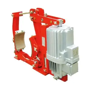
SE Series Electromagnetic Fail-Safe Brake
Need a surge protection recommendation for your brake control cabinet?
If you share: (1) your brake model and coil rating (AC/DC, voltage, current), (2) switching device type (PLC transistor output, relay, contactor), (3) cable length to the brake, and (4) required release/apply timing, we can recommend a practical suppression package (diode vs TVS vs RC vs MOV), placement points, and verification measurements for commissioning.