Retrofit projects often have one hard constraint: you must work with the site’s existing power and control system. That’s why AC/DC dual-use electro-hydraulic thrusters are frequently selected for brake upgrades—especially when the original system voltage or control philosophy has changed over time, or when export projects require different mains standards.
However, “dual-use” does not mean “plug-and-play.” If the thruster is integrated without checking stroke margin, response time, wiring/rectifier behavior, and mechanical linkage geometry, the brake can end up with partial release (dragging), unstable timing, or overheating.
This article explains the practical integration points for retrofit projects using our ZEd series AC/DC dual-use electro-hydraulic thrusters (commonly paired with electro-hydraulic drum brakes like YWZ13 and similar brake families). The goal is simple: make sure the upgraded system releases fully, applies reliably, and matches the site control logic.
1) What “AC/DC dual-use thruster” means in practice
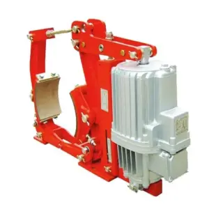
An electro-hydraulic thruster is a self-contained actuator (motor + pump + cylinder) used to open/release a brake. A dual-use thruster is designed to operate under different supply types (depending on model and configuration), which helps in retrofit projects where the control power available may be:
- AC control supply (commonly 220VAC or 380VAC depending on site)
- DC control supply (commonly 110VDC or 220VDC in certain industrial systems)
In retrofit work, the thruster selection is not only about voltage. You must match thrust force and stroke to the brake mechanism, and confirm the response time meets the machine requirement.
[Internal Link Placeholder] ZEd Series AC/DC Dual-Use Electro-Hydraulic Thruster (product page)
2) The four parameters you must match (or the retrofit will not be stable)
When replacing a thruster on an existing brake, these four parameters decide whether the brake will behave correctly:
- Stroke (mm): must achieve full brake release with margin.
- Thrust force (N): must overcome the brake spring force and linkage losses.
- Actuation time: release/apply timing must fit the site’s control logic (especially interlocks).
- Mounting & linkage geometry: pin centers, lever ratios, and alignment must match the brake design.
If any of these are wrong, a brake can still “move” during commissioning, but later drift into dragging and overheating as components warm up and clearances change.
3) Stroke margin: the most common hidden failure in thruster retrofits
Retrofit teams often select the new thruster based on electrical compatibility first, then assume stroke will be fine. In practice, stroke margin is what prevents dragging.
Define three values during retrofit:
- sreq: stroke required to achieve specified clearance (brake fully open)
- savail: available thruster stroke at the installed linkage position
- smargin: safety margin = savail − sreq
Field recommendation: keep a visible margin so that minor wear, temperature expansion, and linkage settling do not push the brake into partial release. If your margin is near zero, expect intermittent dragging complaints.
4) Force matching: why “same stroke” can still fail
Even with correct stroke, the thruster must provide enough force at the working point. In simple terms, to open the brake you need:
F_{thruster} \ge \frac{F_{spring}+F_{friction}}{\eta}Where Fspring is the brake’s spring force requirement, Ffriction includes linkage friction and misalignment losses, and η represents mechanical efficiency of the linkage.
Why retrofits fail here: older brake linkages often have worn pins/bushings, corrosion, or dust packing. That increases friction losses. A new thruster sized only to the original “clean” condition may become marginal after a few months.
Practical check: after installing the new thruster, cycle the brake 20–50 times and confirm it still reaches full clearance without slowing or sticking. If release time drifts upward during cycling, suspect force margin issues or mechanical binding.
5) Electrical integration: what to confirm for AC vs DC control systems
Even for thrusters (motor-driven actuators), wiring and supply quality affect response time and heat. In retrofit projects, confirm these items explicitly:
- Rated supply type and voltage: match the installed ZEd thruster variant to site supply (AC or DC).
- Frequency (AC): 50/60 Hz differences can change motor behavior and stroke timing.
- Voltage at thruster terminals: measure at the thruster, not only at the cabinet (cable drop matters).
- Control interlocks: confirm “brake open” proof (switch) aligns with actual mechanical open position.
If your retrofit includes changing control voltage (for example, moving from 380VAC to 220VAC control), verify that all related components (contactors, relays, brake-open switches, terminal blocks, cable glands) are compatible and correctly labeled.
DKZ Brake Power Supply Box (if your project uses brake rectifiers/power supplies elsewhere)
6) Mechanical integration: mounting, alignment, and linkage geometry
Most retrofit delays happen here, not in electrical wiring. Key points:
- Mounting interface: confirm bolt pattern, mounting height, and allowable misalignment. Avoid forcing alignment with “bolt tension” (it causes binding).
- Pin center distances: small changes can shift lever ratio and required force.
- Lever angle at full release: linkage geometry changes mechanical advantage and can reduce force margin.
- Clearance setting points: after installation, reset shoe clearance/air gap to the brake spec. Don’t keep “old settings.”
Practical tip: witness-mark adjustment nuts and critical bolts after final setting. It makes movement visible during the first week of operation.
7) Commissioning tests that prove the retrofit is successful
After installing a ZEd thruster (or any replacement thruster), run a short commissioning plan that produces defensible data:
- Cold stroke verification: measure savail, confirm clearance achieved, record release/apply time.
- Cycle test: 50 cycles; confirm timing and clearance remain stable.
- Hot check: run the mechanism under typical duty for 30–60 minutes, then verify no drag trend (IR scan + motor current trend).
- Fail-safe check: remove power and confirm brake applies promptly and fully (do this under safe conditions).
Drag detection shortcut: if the brake wheel/disc is significantly hotter than surrounding drivetrain parts during “released” running, treat it as a dragging investigation immediately—retrofit success depends on release margin.
8) Product context: pairing ZEd thrusters with YWZ13 brake retrofits
For many crane travel and conveyor retrofits, the brake body is still mechanically serviceable, but the thruster is aging or mismatched to the available supply. In those cases, upgrading to a correctly matched ZEd AC/DC dual-use thruster can be a practical solution—provided that stroke and force are matched to the brake’s required clearance and spring characteristics.
If your retrofit involves our YWZ13 brake family, share the brake size and current thruster model. We can provide a recommended ZEd match and the measurement points to confirm release margin during commissioning.
[Internal Link Placeholder] ZEd Thruster model selection table (download or product page section)
Need a retrofit checklist for your site power and brake model?
If you provide: (1) existing brake model and size, (2) existing thruster model, (3) available site supply (AC/DC voltage and frequency), (4) target release/apply times, and (5) environment (dust/outdoor/temperature range), we can recommend a ZEd thruster configuration and a commissioning checklist that focuses on stroke margin and drag prevention.