Comprehensive Guide to CQP Series Pneumatic Disc Brakes: Applications, FAQs, and Benefits
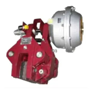
The CQP Series Pneumatic Disc Brakes are a versatile and reliable solution designed for a wide range of industrial applications. These brakes are engineered to provide effective braking and deceleration in various machinery and equipment across industries such as construction, metallurgy, mining, ports, and more. Additionally, they are adept at tension control in cable, paper, and copper sheet machinery.
Key Advantages of CQP Series Brakes
- Efficient Pneumatic Braking System: The CQP series operates on a pneumatic brake and spring release mechanism. This system ensures responsive and precise braking, crucial for safety and performance in industrial settings.
- Compact and Lightweight Design: The brakes feature a simplified overall structure, making them easy to install and maintain. Their compact and lightweight nature does not compromise their strength or efficiency.
- Environmentally Friendly: Equipped with asbestos-free brake pads, the CQP series is designed with sustainability in mind, reducing environmental impact and promoting workplace safety.
- Ease of Maintenance: Brake pads can be installed and replaced swiftly, minimizing downtime. The system also allows for simple adjustments when the brake pads wear down, ensuring consistent performance.
- Automatic Alignment: The brakes are equipped with an automatic alignment feature that maintains equal gaps between the brake block and the main brake disc during operation, enhancing reliability and longevity.
- Versatile Integration: There is no need for a separate power source, as these brakes can be seamlessly integrated with existing pneumatic systems. Additionally, a speed control valve can be added to adjust braking time continuously.
Technical Specifications
The CQP series comes in various models, including CQP10B, CQP20B, CQP38B, and CQPL38B, each offering different specifications to meet diverse requirements:
- CQP10B: Offers rated braking forces ranging from 1065 N to 10680 N, depending on the model variant (A, B, or F) and the pressure applied (2 to 6 bar).
- CQP20B: Similar braking force range, tailored dimensions ensure compatibility with different equipment sizes.
- CQP38B: Provides robust braking solutions with a focus on larger machinery, with the same rated force range.
- CQPL38B: Specifically designed for environments requiring high corrosion resistance, with its rated force and pressure parameters matching other series.
Applications and Usage
The CQP series is ideal for environments with temperatures ranging from -5°C to 40°C and a working pressure not exceeding 7 bar. They are particularly suitable for outdoor applications where rain, snow, or corrosive gases are present, provided a corrosion-resistant model is used. The air supply must be free of oil, water, and other impurities to ensure optimal performance.
Addressing Common Customer Concerns
- Durability and Reliability: The automatic alignment and easy maintenance features ensure the brakes remain effective over time, reducing the need for frequent replacements and ensuring reliability.
- Environmental Adaptability: The CQP series’ ability to operate in various environmental conditions, combined with its eco-friendly design, makes it a robust choice for eco-conscious and diverse industrial settings.
- Integration and Compatibility: The brakes’ compatibility with existing pneumatic systems simplifies installation and reduces additional infrastructure costs, offering a cost-effective solution for businesses.
By addressing these critical factors, the CQP Series Pneumatic Disc Brakes prove to be an invaluable asset in improving operational safety and efficiency across multiple industrial sectors. Their thoughtful design and versatile capabilities make them an excellent choice for businesses looking to enhance their machinery’s braking performance.
Model naming rules
Example Model: CQP200L-B-L
- CQP: This is the prefix for the product model, indicating it is part of the CQP Series Pneumatic Disc Brakes.
- 200: Refers to the disc thickness of 200 mm, which determines the braking force and compatibility with specific machinery.
- L: Indicates that the brake is designed for vertical installation. If “L” is absent, it is for horizontal installation by default.
- B: Represents the structural type. Different letters (e.g., A, B, F) correspond to different designs depending on the equipment’s mechanical requirements.
- L: Refers to the air cylinder installation position, indicating that the air cylinder is installed on the left side. If installed on the right side, it would be marked as “R”.
CQP10B type technical parameters see Table 1, external dimensions see Table 2
( Table 1 )
| CQP10B-A | Braking force N | 3725 | 5415 | 7150 | 8940 | 10680 | Effective radius m | Braking force N.m |
| bar | 2 | 3 | 4 | 5 | 6 | |||
| CQP10B-B | Braking force N | 2110 | 3165 | 4220 | 5275 | 6330 | ||
| bar | 2 | 3 | 4 | 5 | 6 | Brake disc effective radius -0.03 | Braking moment × effective radius | |
| CQP10B-F | Braking force N | 1065 | 1600 | 2133 | 2665 | 3200 | ||
| bar | 2 | 3 | 4 | 5 | 6 |
( Table 2 ) Unit:(mm)
| Size Model | B | D | E | F | ΦG | H | I | J | K | Φd | Φd1 |
| CQP10B-A | 220 | 155 | 10 | 181 | Φ190 | 310 | 39 | 80 | 40 | Φ14 | G3/8 “ |
| CQP10B-B | 200 | 155 | 10 | 181 | Φ150 | 290 | 39 | 80 | 40 | Φ14 | G3/8“ |
| CQP10B-F | 180 | 155 | 10 | 181 | Φ114 | 280 | 39 | 80 | 40 | Φ14 | G1/4“ |
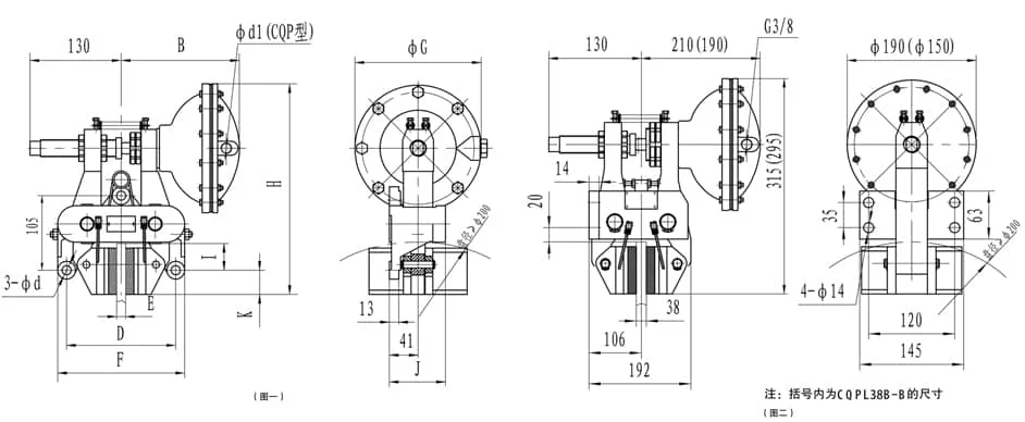
CQP20B technical parameters are shown in Table 3, dimensions are shown in Table 4, and structure is shown in Figure 1
( Table 3 )
| CQP20B-A | Braking force N | 3725 | 5415 | 7150 | 8940 | 10680 | Brake disc effective radius m | Braking torque N.m |
| Air pressure bar | 2 | 3 | 4 | 5 | 6 | |||
| CQP20B-B | Braking force N | 2110 | 3165 | 4220 | 5275 | 6330 | ||
| Air pressure bar | 2 | 3 | 4 | 5 | 6 | Brake disc radius -0.03 | Rated braking force x effective radius | |
| CQP20B-F | Braking force N | 1065 | 1600 | 2133 | 2665 | 3200 | ||
| Air pressure bar | 2 | 3 | 4 | 5 | 6 |
( Table 4 ) Unit: (mm)
| Size Model | B | D | E | F | ΦG | H | I | J | K | Φd | Φd1 |
| CQP20B-A | 220 | 165 | 20 | 192 | Φ190 | 310 | 39 | 90 | 40 | Φ14 | G3/8 “ |
| CQP20B-B | 200 | 165 | 20 | 192 | Φ150 | 290 | 39 | 90 | 40 | Φ14 | G3/8 “ |
| CQP20B-F | 180 | 165 | 20 | 192 | Φ114 | 280 | 39 | 90 | 40 | Φ14 | G1/4“ |
CQP38B technical parameters are shown in Table 5, dimensions are shown in Table 6, and structure is shown in Figure 1
( Table 5 )
| CQP38B-A | Braking force N | 3725 | 5415 | 7150 | 8940 | 10680 | Brake disc effective radius m | Braking torque N.m |
| Air pressure bar | 2 | 3 | 4 | 5 | 6 | |||
| CQP38B-B | Braking force N | 2110 | 3165 | 4220 | 5275 | 6330 | ||
| Air pressure bar | 2 | 3 | 4 | 5 | 6 | Brake disc radius -0.03 | Rated braking force x effective radius | |
| CQP38B-F | Braking force N | 1065 | 1600 | 2133 | 2665 | 3200 | ||
| Air pressure bar | 2 | 3 | 4 | 5 | 6 |
( Table 6 ) Unit: (mm)
| SizeModel | B | D | E | F | ΦG | H | I | J | K | Φd | Φd1 |
| CQP38B-A | 220 | 200 | 38 | 230 | Φ190 | 310 | 39 | 90 | 40 | Φ14 | G3/8 “ |
| CQP38B-B | 200 | 200 | 38 | 230 | Φ150 | 290 | 39 | 90 | 40 | Φ14 | G3/8“ |
| CQP38B-F | 180 | 200 | 38 | 230 | Φ114 | 280 | 39 | 90 | 40 | Φ14 | G1/4“ |
The technical parameters of CQPL38B are shown in Table 7, and the structure and dimensions are shown in Figure 2
( Table 7 )
| CQPL38B-A | Braking force N | 3725 | 5415 | 7150 | 8940 | 10680 | Brake disc effective radius m | Rated braking torque N.m |
| Air pressure bar | 2 | 3 | 4 | 5 | 6 | |||
| CQPL38B-B | Braking force N | 2110 | 3165 | 4220 | 5275 | 6330 | Brake disc radius -0.03 | Rated braking force x effective radius |
| Air pressure bar | 2 | 3 | 4 | 5 | 6 |
Related Products
For comprehensive braking solutions, consider these related products:
- QP Series Pneumatic Caliper Disc Brakes – Pneumatic caliper solution
- SH Series Hydraulic Fail-Safe Disc Brakes – Hydraulic solution
- Ed Series Electro-Hydraulic Thrusters – Precision power and control