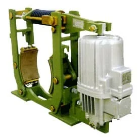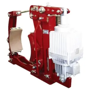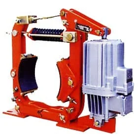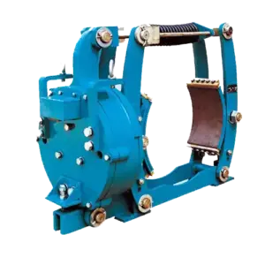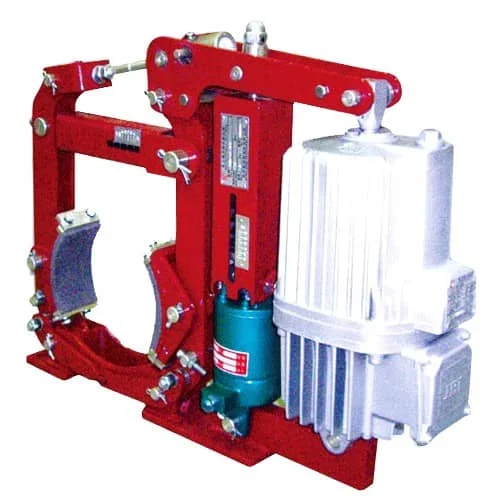
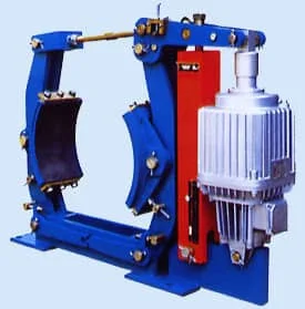

The YWZ13 series electric hydraulic drum brake is engineered for the demanding, high-frequency applications that define port terminals, steel mills, and mining operations. Designed for reliable performance under continuous heavy-duty cycling, the YWZ13 delivers 100 to 2500 N·m of braking torque while withstanding the harsh conditions that quickly destroy lesser brakes.
Featuring compatibility with Ed series electro-hydraulic thrusters and optional automatic lining wear compensation (M), the YWZ13 maintains consistent braking performance throughout its service life—reducing maintenance intervals and unexpected downtime in operations where every minute of availability counts.
Key Specifications at a Glance
| Parameter | Specification |
|---|---|
| Braking Torque Range | 100 – 2500 N·m |
| Brake Wheel Diameter | 200 – 500 mm |
| Operating Temperature | -20°C to +50°C |
| Relative Humidity | ≤ 90% |
| Thruster Compatibility | Ed series (standard, explosion-proof available) |
| Installation Standard | JB/ZQ4388-1997 |
| Options | Auto wear compensation, manual release, limit switches |
Why Choose YWZ13 Series Drum Brakes?
1. Built for High-Frequency, Heavy-Duty Cycling
The YWZ13 series is specifically engineered for applications that demand continuous, high-frequency braking cycles. Unlike brakes designed for occasional use, the YWZ13 features reinforced components, optimized heat dissipation, and durable friction materials that withstand the punishing duty cycles typical of:
- Container port cranes performing 50+ cycles per hour
- Steel mill cranes handling molten metal in continuous operation
- Mining hoists ascending and descending with heavy mineral loads
2. Optional Automatic Wear Compensation
The automatic lining wear compensation device (M option) is a critical feature for high-cycle applications. As brake linings wear during continuous operation, the YWZ13-M automatically adjusts the brake mechanism to maintain consistent clearance and braking torque—eliminating the manual adjustment intervals that would otherwise interrupt operations.
This feature is especially valuable for:
- Multi-shift operations where maintenance windows are limited
- Remote mining locations where frequent servicing is costly
- Port operations running 24/7 during peak shipping seasons
3. Flexible Manual Release Options
The YWZ13 offers configurable manual release to suit your installation and operational requirements:
- S1: Left-side manual release device
- S2: Right-side manual release device
- S1 + S2: Dual manual release for flexible positioning
Manual release is essential for installation, commissioning, power failures, and maintenance operations where hydraulic power is unavailable.
4. Integrated Limit Switches
Optional limit switches provide real-time status feedback to PLC control systems:
- K1: Brake open (rising) limit switch
- K2: Brake close (lowering) limit switch
- K3: Lining wear limit indication switch
These signals enable automated monitoring and predictive maintenance scheduling, reducing unexpected brake failures.
YWZ13 Series Model Specifications
Select the optimal YWZ13 model based on your required braking torque, brake wheel diameter, and thruster configuration.
| Model | Brake Wheel (mm) | Thruster | Braking Torque (N·m) | Weight (kg) |
|---|---|---|---|---|
| YWZ13-200/E23 | 200 | Ed 23/5 | 100-200 | 32 |
| YWZ13-200/E30 | 200 | Ed 30/5 | 140-315 | 43 |
| YWZ13-300/E30 | 300 | Ed 30/5 | 250-400 | 65 |
| YWZ13-300/E50 | 300 | Ed 50/6 | 400-630 | 80 |
| YWZ13-300/E80 | 300 | Ed 80/6 | 630-1000 | 92 |
| YWZ13-400/E50 | 400 | Ed 50/6 | 400-800 | 125 |
| YWZ13-400/E80 | 400 | Ed 80/6 | 800-1250 | 145 |
| YWZ13-400/E121 | 400 | Ed 121/6 | 1000-2000 | 180 |
| YWZ13-500/E80 | 500 | Ed 80/6 | 800-1600 | 195 |
| YWZ13-500/E121 | 500 | Ed 121/6 | 1250-2500 | 220 |
Note: All models available with BEd explosion-proof thrusters for hazardous environments. Contact our engineering team for custom configurations or additional options.
YWZ13 Series vs YWZ4 vs YWZ9: Which Series is Right for You?
| Feature | YWZ13 Series | YWZ4 Series | YWZ9 Series |
|---|---|---|---|
| Torque Range | 100 – 2500 N·m | 100 – 8000 N·m | 200 – 16000 N·m |
| Key Advantage | High-cycle, auto compensation option | Versatile, proven design | Maximum torque, auto compensation |
| Max Torque | 2500 N·m | 8000 N·m | 16000 N·m |
| Auto Wear Comp. | Optional (M code) | Not available | Standard feature |
| Best For | High-frequency port/mining | General industrial | Heavy-duty, critical lifting |
Choose YWZ13 when: You need high-cycle performance with optional automatic wear compensation for port cranes, mining hoists, or steel mill equipment operating under continuous heavy-duty conditions.
Primary Applications
Port & Container Handling
The YWZ13 is the preferred brake for ship-to-shore (STS) cranes, rubber-tyred gantry (RTG) cranes, and straddle carriers in container terminals. The high-frequency cycling capability handles the demanding duty cycles of modern container handling—50+ cycles per hoist, hundreds of trolley travels per shift—without the maintenance headaches that plague lesser brakes.
Metallurgy & Steel Mills
In steel mills and foundries, the YWZ13 provides reliable braking for charging cranes, overhead cranes, and material handling equipment. The optional explosion-proof thruster (BEd series) ensures safe operation in environments where flammable atmospheres may be present during steel production.
Mining & Bulk Material Handling
Mining hoists, conveyors, and stackers-reclaimers depend on YWZ13 brakes for reliable stopping in remote, harsh environments. The automatic wear compensation option (YWZ13-M) is particularly valuable in underground mines where maintenance access is difficult and every hour of production matters.
Water Conservancy & Sluice Gates
The YWZ13 controls sluice gates and dam equipment in water management applications where reliable braking is essential for flood control and power generation infrastructure.
Model Code Guide
Understanding the YWZ13 model code helps you specify the exact configuration for your application:
| Code Element | Example | Description |
|---|---|---|
| Series | YWZ13 | 13th generation electro-hydraulic drum brake |
| Brake Wheel | 300 | 300 mm brake wheel diameter |
| Actuator Type | E | E = Standard Ed series, B = Explosion-proof |
| Thrust Code | 50 | Ed 50/6 thruster |
| Options | M, K1, S1 | M = Auto wear comp., K1 = Open limit, S1 = Left manual |
Example: YWZ13-300/E50MK1S1 indicates a YWZ13 series brake with 300mm wheel, Ed50 thruster, automatic wear compensation, open limit switch, and left-side manual release.
Frequently Asked Questions
What is the difference between YWZ13 and YWZ4 drum brakes?
What does the M (automatic wear compensation) option do?
What limit switches are available for YWZ13?
Can YWZ13 brakes use explosion-proof thrusters?
What is the typical service life of YWZ13 brake linings?
Related Products & Accessories
Complete your high-performance braking system with these compatible products:
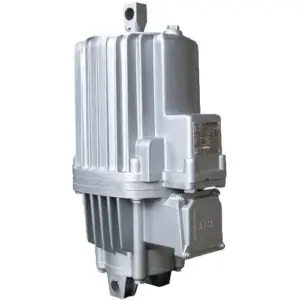
- Ed Series Electro-Hydraulic Thrusters – Standard thrusters for YWZ13 brakes
- BEd Explosion-Proof Electric Hydraulic Actuator – ATEX-certified thrusters for hazardous areas
- YWZ9 Series Electric Hydraulic Drum Brake – Heavy-duty option for critical lifting applications
- YWZ4 Series Electric Hydraulic Drum Brakes – Versatile option for general industrial use
- ZDL Series Brake Wheels – Compatible brake wheels for YWZ13 series
Request a Quote for YWZ13 Series Drum Brakes
Get the high-performance braking your port, metallurgy, or mining operation demands. Our engineering team can help you select the optimal YWZ13 configuration—including automatic wear compensation options and limit switch combinations—for your specific application requirements.
Contact us today to discuss your high-frequency braking requirements, request dimensional drawings, or receive a detailed quotation for YWZ13 series drum brakes.