Many brake “failures” reported on site are not manufacturing defects—they’re acceptance and installation misses: wrong coil voltage, shipping locks left in place, incomplete release due to linkage geometry, friction surfaces contaminated during handling, or fasteners that loosen after the first hot run.
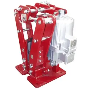
This article provides a practical on-site acceptance checklist focused on what is most commonly overlooked: identification (nameplate & configuration), clearances, fasteners, and accessories. Examples are aligned with our brake families such as YWZ13 electro-hydraulic drum (block) brakes, SH hydraulic fail-safe disc brakes, and SE electromagnetic fail-safe brakes.
[Image Placeholder] Field acceptance toolkit: feeler gauges, calipers, multimeter, clamp meter, torque wrench, dial indicator, IR thermometer, thread marker paint.
1) Receiving inspection (before installation): catch the “wrong part / wrong configuration” issues
Do this before the brake is mounted to the machine. Once installed, tracing mismatches takes hours (and usually ends in “it must be the brake”).
- Check nameplate: model, serial number, voltage, frequency, duty, release pressure (if applicable), protection rating, and any special configuration notes.
- Verify documents match the serial: factory test sheet, wiring diagram, installation drawing, and packing list.
- Shipping damage: bent linkage arms, cracked connectors, dented thruster/cylinder, damaged cable glands, missing fasteners, torn seals.
- Friction surfaces are clean: pads/linings and disc/brake wheel should not have anti-rust oil, grease, or packaging adhesive residue.
- Accessories are present: manual release hardware, limit switches, wear switches, hydraulic fittings, connectors, protective covers (if ordered).
Practical rule: photograph the nameplate and terminal box before installation. It prevents long disputes later and speeds up remote troubleshooting.
2) Identification checks that prevent 80% of electrical/actuation problems
On site, “it powers on” is not enough. You want to confirm the brake’s configuration matches your power system and controls.
| Brake type | Most-missed parameter | What to verify on site | Typical symptom if wrong |
|---|---|---|---|
| Electromagnetic brake (e.g., SE) | Coil voltage / rectifier match | Measure coil DC voltage at brake terminals during release | Weak release, dragging, coil overheating |
| Electro-hydraulic thruster brake (e.g., YWZ13) | Power phase / rotation / stroke | Confirm correct wiring, stroke achieved, no mechanical bind | Slow release, partial release, overheating |
| Hydraulic fail-safe brake (e.g., SH) | Release pressure / bleed condition | Confirm pressure reaches spec and brake fully releases | Cannot release, pad drag, unstable operation |
[Internal Link Placeholder] If your electromagnetic brake uses a dedicated power supply box/rectifier, link it here (example: DKZ power supply box page).
3) Clearance and alignment: measure it, don’t “eyeball” it
Clearance (air gap/shoe clearance) is a small number with big consequences:
- Too small → dragging → temperature rise → fade → rapid wear
- Too large → delayed braking → longer stopping distance → insufficient holding response
For drum/block brakes (e.g., YWZ13): shoe clearance symmetry matters
For YWZ13 electro-hydraulic drum brakes, measure left/right shoe clearance with a feeler gauge at the recommended points. Record both sides. A large imbalance often predicts uneven wear and inconsistent torque.
[Image Placeholder] Where to place the feeler gauge on a drum brake shoe (two points per side) + example recording format.
For disc brakes (e.g., SH): confirm full release and stable pad clearance
For SH hydraulic fail-safe disc brakes, confirm the pads retract properly after release and the disc runs freely without hot rubbing. If you have a dial indicator, also check disc runout—excessive runout can “pump” pads and change effective air gap during rotation.
Field tip (high value, low cost): after release, rotate the shaft by hand (or jog at low speed) and listen. Continuous rubbing sound + rising motor current is often the earliest warning of drag.
4) Fasteners: torque control and re-check timing (the part people skip)
Brakes see vibration, thermal cycling, and repeated shock loads. Even when factory-tightened, site mounting fasteners should be verified with a torque wrench and then re-checked after the first thermal run.
What to do on site:
- Torque the mounting bolts to your project spec (and record it). Use calibrated tools.
- Mark fasteners with torque paint (witness marks). This makes loosening visible during inspections.
- Re-torque after hot run: run the mechanism for 30–60 minutes under typical load, then re-check critical bolts after cooling.
Reference data (example only): if your project doesn’t provide bolt torque values, you can use standard tables based on bolt grade, lubrication state, and thread condition. Because site conditions vary, the safest practice is to follow your machine OEM torque spec.
| Common bolt (property class) | Dry torque (approx.) | Where it matters on brakes |
|---|---|---|
| M12 (8.8) | ~70–90 N·m | Caliper brackets, guards, sensor mounts |
| M16 (8.8) | ~180–220 N·m | Main mounting to base, brake arms |
| M20 (8.8) | ~350–450 N·m | Large brake frames / heavy mounts |
If you need a quick estimation model to sanity-check torque planning, a common engineering approximation is:
T_b \approx K \, F \, d
Where K (nut factor) can vary widely (often ~0.15–0.25 depending on lubrication and surface condition). This is why project-specific torque specs matter.
5) Accessories & peripherals: confirm they actually work (not just “installed”)
Many sites check only the brake body. But peripherals are what make the system safe and maintainable.
- Manual release: verify it is present, accessible, and returns correctly (especially on fail-safe brakes).
- Brake-open switch (if equipped): confirm it changes state only when the brake is fully released (prevents “move while half-open”).
- Wear switch: confirm wiring and alarm logic; check mechanical actuation direction.
- Power supply/rectifier: confirm output at the brake terminals (not just panel voltage).
- Hydraulic lines/fittings: check correct hose routing (no rubbing, no sharp bends), correct sealing, correct bleed points.
- Transport locks / shipping blocks: confirm removed (a frequent cause of “no stroke / no release”).
[Image Placeholder] Example: shipping block / transport screw locations on a thruster + “remove before operation” tag.
6) Functional checks you should run during acceptance (quick, measurable, and defensible)
A good on-site acceptance test uses measurable outcomes. Below is a practical sequence that fits most installations.
Step 1: Cold cycling (10–20 cycles)
- Confirm smooth apply/release, no sticking, no abnormal noise.
- Record basic timing: release time and apply time (use a stopwatch if no PLC log).
- Confirm clearance after cycling does not drift abnormally.
Step 2: Fail-safe behavior check (mandatory for hoisting / safety holding)
For fail-safe systems (e.g., SH and many spring-applied designs), verify that loss of power / loss of release pressure causes the brake to apply correctly and hold. Perform this test under controlled conditions with the machine secured.
Step 3: Hot check (the fastest way to detect dragging)
Operate the mechanism in a realistic manner for 30–60 minutes (or to the point where the brake has clearly warmed), then:
- Use an IR thermometer to scan the disc/brake wheel and housing for unusual hot spots.
- Verify motor current has not increased compared to baseline (dragging often shows up here first).
- Re-check clearance after cooling and confirm fasteners are still witness-aligned.
Useful field threshold: if a brake surface is significantly hotter than nearby drivetrain components under “released” running, treat it as a drag investigation—even if stopping feels normal.
7) The “small details” list that causes the biggest on-site delays
- Wrong voltage at the brake terminals: panel says 220V, but the brake sees lower due to cable drop → weak release.
- Transport plug not vented / wrong thruster preparation: causes slow or inconsistent stroke.
- Anti-rust oil on disc or lining: causes slip, glazing, and unstable torque.
- Brake installed off-center / misaligned bracket: creates uneven wear and hot spots.
- Limit switch logic reversed: “brake open” signal present while brake is still partially applied.
- Fasteners not re-checked after first hot run: loosening causes geometry drift and dragging.
Want a model-specific acceptance sheet for your brake?
If you share your brake model and application (hoist / trolley / travel / wind), we can provide an acceptance checklist with the correct measurement points and recommended recorded values (clearance points, wiring checks, fail-safe verification steps), tailored for our brake series such as YWZ13, SH, and SE.
[Internal Link Placeholder] Download: On-site Acceptance Checklist (labels + clearance + fasteners + accessories) in Excel/PDF.