Добро пожаловать в окончательное руководство по терминологии промышленных тормозов. Независимо от того, являетесь ли вы инженером, проектирующим новый кран, техником по обслуживанию, устраняющим неполадки конвейера, или менеджером по закупкам, который ищет новые компоненты, понимание языка тормозов имеет решающее значение для безопасности, эффективности и производительности.
Этот глоссарий предназначен для того, чтобы стать вашим основным ресурсом. Мы организовали термины в логические категории, чтобы помочь вам создать полное понимание того, как работают эти критически важные системы.
Основные концепции и принципы
1. Момент (тормозной момент)
Вращательная сила, которую тормоз может приложить для остановки вращающегося элемента, такого как вал или колесо. Это наиболее критическое значение при выборе тормоза и обычно измеряется в Ньютон-метрах (Нм) или фунт-футах (фунт-фут).
2. Тормоз с защитой от отказа
Тормоз, который включается силой пружины и отключается внешним источником энергии (например, гидравлической, пневматической или электрической). Если питание отключается, пружины автоматически применяют тормоз, “сбивая” в безопасное, заблокированное состояние. Это стандарт для подъемных приложений. Узнайте больше о наших Решениях тормозов с защитой от отказа .
3. Рабочий тормоз (динамический тормоз)
Тормоз, предназначенный для замедления и остановки движущихся механизмов в процессе нормальной работы. Он должен быть способен поглощать и рассеивать большие количества кинетической энергии в виде тепла.
4. Парковочный тормоз (статический / удерживающий тормоз)
Тормоз, предназначенный в первую очередь для удержания нагрузки или машины в неподвижном состоянии после того, как она уже была остановлена. Он имеет высокий удерживающий момент, но обычно меньшую тепловую емкость, чем рабочий тормоз.
5. Аварийный тормоз
Система тормозов, предназначенная для остановки машины в случае отключения питания или отказа основного тормоза. Тормоза с защитой от отказа часто выполняют эту функцию.
6. Цикл работы
Мера частоты и продолжительности тормозных приложений за определенный период. Высокий рабочий цикл (например, много остановок в час) требует тормоза с отличной тепловой емкостью.
7. Тепловая емкость
Способность тормоза поглощать и рассеивать тепло, генерируемое во время торможения, без ухудшения его производительности. Превышение этой емкости приводит к ухудшению торможения.
8. Обычно открытый тормоз
Тормоз, который отключен (открыт) в своем спокойном состоянии и требует энергии для включения (закрытия). Эти тормоза используются для рабочей торможения, где функция защиты от отказа не требуется.
9. Обычно закрытый тормоз
Еще один термин дляТормоза с защитой от отказа. Он включен (закрыт) в своем спокойном, безэнергетическом состоянии.
Типы тормозов и приводов
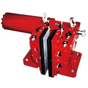
10. Дисковый тормоз
Тормоз, который использует калипры для сжатия накладок против вращающегося диска или ротора. Известен отличным рассеиванием тепла и стабильной производительностью. Ознакомьтесь с нашим ассортиментомПромышленных дисковых тормозов.
11. Барабанный тормоз
Тормоз, который использует колодки для прижатия к внутренней поверхности вращающегося барабана. Известен высоким моментом в компактном дизайне и хорошей защитой от окружающей среды. Изучите нашиПромышленные барабанные тормоза.
12. Калипровочный тормоз
Сборка в системе дискового тормоза, которая содержит тормозные колодки и поршни. Она преобразует гидравлическое или пневматическое давление в силу зажима на диске.
13. Блочный тормоз
Тип барабанного тормоза, где шарнирные рычаги прижимают блоки или колодки к внешней поверхности тормозного колеса. Распространен в кранах и тяжелом оборудовании.
14. Ленточный тормоз
Тормоз, который использует гибкую металлическую ленту, обшитую фрикционным материалом, которая обвивается вокруг внешней стороны барабана для создания тормозной силы.
15. Шторный тормоз (ветрозащитный тормоз)
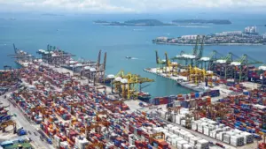
Мощная, вторичная тормозная система, используемая на крупных, рельсовых машинах, таких как портовые краны, чтобы предотвратить их движение под воздействием сильного ветра. Ознакомьтесь с нашимиРешениями шторных тормозов.
16. Зажим для рельса
Тип шторного тормоза, который использует мощные захваты для зажима непосредственно на головке рельса, обеспечивая очень высокую удерживающую силу.
17. Клинный тормоз
Тип шторного тормоза, где клин зажимается между тормозной колодкой и рельсом, создавая огромную, самоукрепляющую тормозную силу.
18. Электрогидравлический толкатель
Автономный актуатор, который использует электрический мотор для привода гидравлического насоса, который, в свою очередь, перемещает поршень для освобождения тормоза с защитой от отказа. НашиСерии ЭД Толкателейявляются стандартом в отрасли.
19. Актуатор
Общее название для любого компонента, который обеспечивает силу для работы тормоза (например, толкатель, гидравлический цилиндр, пневматический цилиндр или электромагнит).
20. Соленоид / Электромагнит
Актуатор, который использует электрическую катушку для создания магнитного поля, которое тянет плунжер для включения или отключения тормоза.
Ключевые компоненты и детали
21. Накладка трения (колодка / обувь)
Расходный материал, прикрепленный к тормозной колодке или обуви, который непосредственно контактирует с диском или барабаном. Его коэффициент трения определяет тормозную силу.
22. Тормозной диск (ротор)
Вращающийся диск в системе дискового тормоза, к которому прижимаются колодки.
23. Тормозной барабан / Колесо
Вращающийся цилиндр в системе барабанного тормоза, к которому прижимаются колодки.
24. Калипровка
C-образный корпус для колодок и поршней в дисковом тормозе.
25. Тормозная колодка
Корпус, обычно полукруглый, к которому заклепана или приклеена накладка трения в барабанном тормозе.
26. Шарнирный штифт
Штифты и валы, на которых рычаги тормоза и соединения вращаются. Правильная смазка имеет решающее значение.
27. Пружина
Компонент, который обеспечивает силу для включения тормоза с защитой от отказа. Его сжатие определяет тормозной момент.
28. Связка
Система рычагов и рычагов, которая передает силу от актуатора к тормозным колодкам или накладкам.
29. Воздушный зазор
Небольшой зазор между накладкой трения и диском/барабаном, когда тормоз освобожден. Это должно быть правильно отрегулировано по мере износа накладки.
30. Соединение
Устройство, используемое для соединения двух валов, часто там, где установлен тормоз (например, между двигателем и редуктором).
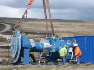
Гидравлическая силовая установка
Автономная система, которая генерирует гидравлическое давление, необходимое для работы одного или нескольких крупных гидравлических тормозов.
Показатели эффективности и термины устранения неисправностей
32. Ухудшение торможения
Потеря тормозной эффективности, которая происходит, когда тормоз перегревается, что приводит к снижению коэффициента трения накладок.
33. Глазурь
Состояние, при котором перегрев вызывает затвердевание, сглаживание и блеск поверхности трения, что значительно снижает ее способность генерировать трение.
34. Визг
Высокочастотный звук, вызванный высокочастотными вибрациями между накладкой трения и диском/барабаном.
35. Шум / Дребезжание
Низкочастотная, сильная вибрация, ощущаемая во время торможения, часто вызванная загрязнением, деформированными компонентами или неправильной регулировкой.
36. Загрязнение
Наличие масла, жира, воды или других посторонних веществ на поверхностях трения, что резко снижает тормозной момент.
37. Трение
Состояние, при котором тормоз не полностью освобождается, что приводит к тому, что накладки остаются в контакте с диском/барабаном, что приводит к быстрому перегреву и износу.
38. Ход
Расстояние, на которое перемещается поршень или плунжер актуатора для освобождения тормоза. Недостаточный ход может привести к трению; чрезмерный ход может означать, что накладки изношены.
39. Компенсация износа
Механизм, ручной или автоматический, который регулирует соединение тормоза для поддержания правильного воздушного зазора по мере износа накладок трения.
40. Пробивка (обработка)
Процесс правильного износа новых накладок тормоза и дисков/барабанов для обеспечения полного контакта и оптимальной производительности.
41. Коэффициент трения (µ)
Безразмерное значение, представляющее собой отношение силы трения между двумя телами к силе, прижимающей их друг к другу. Более высокий µ означает большую тормозную силу.
42. Самоэнергетический
Характеристика некоторых конструкций барабанных тормозов, где вращение барабана помогает прижать одну из колодок плотнее к нему, увеличивая тормозную силу.
43. ATEX / Взрывозащита
Сертификация для оборудования, предназначенного для безопасного использования в потенциально взрывоопасных атмосферах, таких как шахты или химические заводы. Ознакомьтесь с нашимиВзрывозащищенными толкателями.
44. Рейтинг IP (защита от проникновения)
Стандарт, который оценивает степень защиты компонента от проникновения посторонних объектов (таких как пыль) и влаги.
45. Зазор
Зазор или “игра” в механической системе, такой как соединение тормоза.
46. Гистерезис
Запаздывание эффекта за его причиной. В тормозах это может относиться к задержке включения или отключения после подачи управляющего сигнала.
47. Время отклика
Время, прошедшее с момента, когда подается сигнал на торможение, до момента, когда тормоз достигает полного момента.
48. Время установки / Время освобождения
Конкретное время, необходимое для полного включения (установки) или отключения (освобождения) тормоза.
49. Статический момент
Момент, необходимый для удержания нагрузки в неподвижном состоянии (то же самое, что и удерживающий момент).
50. Динамический момент
Момент, который тормоз может приложить к вращающейся нагрузке (то же самое, что и рабочий или тормозной момент).