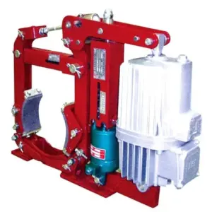

The ZWZ3 series DC electromagnetic drum brake is engineered for demanding industrial applications where reliable stopping power, high duty cycles, and robust construction are essential requirements. With a braking torque range from 35 to 7100 N·m and compliance with GB6334-86 and JB/T7685-2006 standards, the ZWZ3 provides the heavy-duty performance needed in steel mills, mining operations, port facilities, and construction machinery.
Featuring DC electromagnetic operation with flexible power supply options (DC220V or DC110V), the ZWZ3 series offers simple, reliable braking without the complexity of hydraulic systems. The series includes both parallel coil (Type-1) and parallel+series coil (Type-2) configurations to match your specific control requirements.
Key Specifications at a Glance
| Parameter | Specification |
|---|---|
| Braking Torque Range | 35 – 7100 N·m |
| Brake Wheel Diameter | 160 – 800 mm |
| Duty Cycle | Up to 50% continuous operation |
| Rated Voltage | DC220V (standard), DC110V available |
| Operating Temperature | -25°C to +40°C (standard) |
| Protection Grade | IP65 (standard) |
| Standards | GB6334-86, JB/T7685-2006 |
Why Choose ZWZ3 Series DC Electromagnetic Drum Brakes?
1. High Torque Range for Heavy-Duty Applications
The ZWZ3 series delivers 35 to 7100 N·m of braking torque across brake wheel diameters from 160mm to 800mm. This extensive range covers applications from light machinery to massive heavy industrial equipment:
- Small to medium cranes (35-400 N·m)
- Heavy-duty industrial cranes (400-2500 N·m)
- Massive steel mill and mining equipment (2500-7100 N·m)
2. 50% Duty Cycle for Continuous Operation
Unlike brakes designed for intermittent operation, the ZWZ3 series supports up to 50% duty cycle for sustained engagement applications. This makes it ideal for:
- Parking brakes holding heavy loads for extended periods
- Emergency stop systems requiring continuous engagement
- Conveyor belt holding brakes
- Rotary kiln and dryer holding brakes
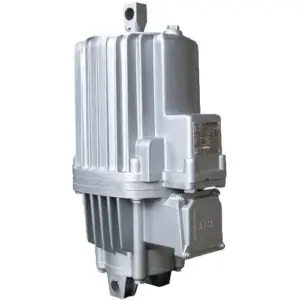
3. DC Electromagnetic Simple Operation
The ZWZ3 uses proven DC electromagnetic technology:
- No hydraulic system – Eliminates pumps, hoses, and hydraulic fluid
- Direct electrical control – Simple on/off operation via contactors
- DC220V or DC110V power supply flexibility
- Fast response – Rapid brake engagement for emergency stops
4. Two Configuration Options
The ZWZ3 series offers both Type-1 (parallel coil) and Type-2 (parallel+series coil) configurations:
- Type-1 (Parallel Coil): Simple control, easy maintenance, standard applications
- Type-2 (Parallel+Series Coils): Enhanced control flexibility, adjustable braking force for complex control schemes
ZWZ3 Model Naming Guide
Type-1 (Parallel Coil) Models
Format: ZWZ3 – [Wheel Diameter]/[Electromagnet Model]
Example: ZWZ3-160/100
- Wheel diameter: 160 mm
- Electromagnet model: 100
Type-2 (Parallel + Series Coil) Models
Format: ZWZ3 – [Wheel Diameter]/[Electromagnet Model][Coil Type]
Example: ZWZ3-400/500I (parallel) or ZWZ3-630/500II (series)
- Wheel diameter: 400 mm or 630 mm
- Electromagnet model: 500
- Coil configuration: I (parallel) or II-VII (series variations)
ZWZ3 Series Model Specifications
| Model | Brake Wheel (mm) | Torque @ 25% ED (N·m) | Torque @ 40% ED (N·m) | Weight (kg) |
|---|---|---|---|---|
| ZWZ3-160/100 | 160 | 35.5 | 28 | 13 |
| ZWZ3-160/200 | 160 | 140 | 112 | 22 |
| ZWZ3-200/100 | 200 | 40 | 31.5 | 26 |
| ZWZ3-200/200 | 200 | 160 | 125 | 35 |
| ZWZ3-315/200 | 315 | 250 | 200 | 60 |
| ZWZ3-315/300 | 315 | 450 | 355 | 75 |
| ZWZ3-400/400 | 400 | 710 | 560 | 120 |
| ZWZ3-400/500 | 400 | 1120 | 900 | 145 |
| ZWZ3-500/500 | 500 | 1400 | 1120 | 180 |
| ZWZ3-630/630 | 630 | 2800 | 2240 | 280 |
| ZWZ3-800/800 | 800 | 4500 | 3550 | 420 |
| ZWZ3-800/900 | 800 | 7100 | 5600 | 520 |
Note: ED = Duty Cycle. Longer brake wheels and larger electromagnets available. Contact our engineering team for specific requirements.
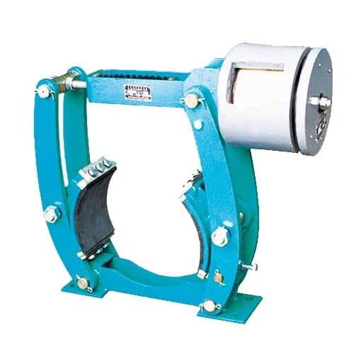
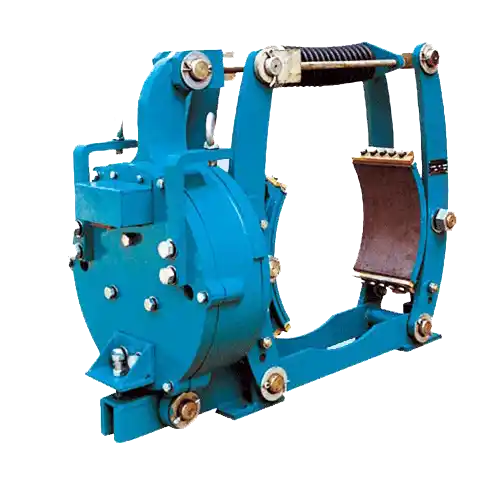
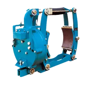
How ZWZ3 DC Electromagnetic Brakes Work
Spring-Applied Principle
The ZWZ3 series uses a spring-applied, electromagnetically released design:
- Brake Engagement (Power Off): Powerful springs push the brake shoes against the drum, creating friction that generates the braking torque
- Brake Release (Power On): When DC power is applied to the electromagnet, the magnetic force overcomes spring pressure, lifting the brake shoes from the drum
- Fail-Safe Operation: Any loss of electrical power causes immediate brake engagement—critical for safety applications
Type-2 Enhanced Control
Type-2 models with parallel+series coils provide enhanced control options:
- Series coil: Provides initial holding force with lower current
- Parallel coil: Adds additional force for full engagement
- Variable braking: Can be controlled with reduced voltage for partial engagement
Primary Applications
Mining & Bulk Material Handling
The ZWZ3 is the workhorse brake for mining equipment including conveyors, Crushers, hoists, and stackers-reclaimers. The 50% duty cycle handles continuous holding requirements while the robust construction withstands the dust, vibration, and harsh conditions of mining operations.
Metallurgy & Steel Mills
In steel mills and foundries, the ZWZ3 provides reliable holding brakes for rolling mills, hot metal handling, and processing equipment. The high torque capacity handles the massive loads involved in steel production while the simple DC operation ensures reliability in the demanding mill environment.
Port & Container Handling
Port cranes, shipyard equipment, and container handling machinery rely on ZWZ3 brakes for their combination of high torque, simple operation, and proven reliability in marine environments.
Construction & Heavy Machinery
Tower cranes, crawler cranes, and heavy construction equipment use ZWZ3 brakes for reliable stopping in demanding field conditions.
Frequently Asked Questions
What is the difference between ZWZ3 Type-1 and Type-2 models?
Type-1 (parallel coil) models have a single electromagnet coil connected in parallel. Type-2 (parallel+series coil) models have two coils that can be connected in series or parallel, providing more flexible control options. Type-1 is simpler and easier to maintain; Type-2 allows variable braking force and can operate with reduced voltage for partial engagement.
What does duty cycle (ED) mean for ZWZ3 brakes?
Duty cycle (ED) indicates the percentage of time the brake can be energized versus the total cycle time. ZWZ3 brakes support up to 50% ED for sustained engagement applications. A higher ED percentage means the brake can remain engaged longer without overheating. For example, at 25% ED with 4-minute cycles, the brake can be energized for 1 minute per cycle.
Can ZWZ3 brakes operate on AC power?
No, ZWZ3 brakes are DC electromagnetic devices designed for DC power supply (DC220V or DC110V standard). If only AC power is available, a rectifier must be used to convert AC to DC. Takebrakes offers DKZ power supply boxes that include rectifiers for AC-to-DC conversion.
What is the difference between ZWZ3 and electro-hydraulic drum brakes like YWZ4?
ZWZ3 uses DC electromagnetic force to release the brake (spring-applied, electromagnetically released), while YWZ4 uses an electro-hydraulic thruster. ZWZ3 advantages: simpler (no hydraulic system), faster response, better for holding/parking. YWZ4 advantages: higher torque capacity, smoother engagement, better for high-frequency cycling.
What maintenance does ZWZ3 require?
ZWZ3 brakes require minimal maintenance: (1) Regular inspection of brake shoes for wear, (2) Check electrical connections and coil resistance periodically, (3) Verify spring tension and brake clearance, (4) Clean brake mechanism of dust and debris. The electromagnetic design has no hydraulic fluid to check or replace, reducing maintenance compared to hydraulic brakes.
Related Products & Accessories
Complete your braking system with these compatible products:
- YWZ4 Series Electric Hydraulic Drum Brakes – Electro-hydraulic alternative for high-frequency cycling
- YWZ9 Series Electric Hydraulic Drum Brake – Heavy-duty electro-hydraulic option
- DKZ Power Supply Boxes – AC to DC rectification for ZWZ3 brakes
- ZDL Series Brake Wheels – Compatible brake wheels for ZWZ3 series
Request a Quote for ZWZ3 Series DC Electromagnetic Drum Brakes
Get the heavy-duty DC electromagnetic braking solution your industrial application demands. Our engineering team can help you select the optimal ZWZ3 model based on your torque requirements, duty cycle, and control configuration needs.
Contact us today to discuss your application, request dimensional drawings, or receive a detailed quotation for ZWZ3 series DC electromagnetic drum brakes.